- 浏览: 4814161 次
- 性别:

- 来自: 济南
-

最新评论
-
wahahachuang8:
GoEasy 实时推送支持IE6-IE11及大多数主流浏览器的 ...
服务器推送技术 -
pdztop:
inffas32.asm(594) inffas32.asm( ...
zlib 在 Visual Studio 2005 下编译失败的解决办法 -
myangle89:
这个方法有效果,但还是绕了一大圈。另外:如果每次这样使用,会造 ...
利用 Spring 与 Log4J 巧妙地进行动态日志配置切换并立即生效 -
lsw521314:
亲,请把用到的包贴出来好么?这版本问题搞得我头大······· ...
lucene MMAnalyzer 实现中文分词 -
guji528:
多命令执行:cmd /k reg delete "H ...
REG Command in Windows XP - Windows XP REG命令的作用和用法
Whether your system boundaries are blurred or you've tangled your use cases in user-interface screens, you'll soon find that the first time you model it's easy to fall into some fairly predictable problem areas. Luckily for you, it's also easy enough to avoid them.
Use cases are an increasingly popular technique for documenting system and software requirements. With their simple graphical notation and accessible natural-language specifications, use cases are attractive to development teams–even those with little experience in formal requirements specification. This simplicity can be deceptive, however. Although project teams have little trouble getting started with use cases, many of them encounter similar problems in applying them on a larger scale.
While learning from experience may be a powerful thing, it’s an expensive pedagogical technique in the business world. Your project team doesn’t have to experience the 10 most common pitfalls firsthand. I have four recommendations that will help prevent many of the common use-case pitfalls, and one recommendation that will help you detect and remove them.
Where’s the System?
Be explicit about the system boundary. The use-case model has a trivial notation. In its simplest form, it’s just a labeled box that indicates the system boundary, with actors (stick figures) drawn outside of this box and the use cases (labeled ellipses) inside. Lines or arrows connect the actors to the use cases.
|
The Top 10 Use-Case
Pitfalls
1. The system boundary
is undefined or inconstant. |
But what is this labeled box that we call the system? Are we talking about a computer system? An application? A subsystem? Or a whole business enterprise? Use cases might legitimately be used to describe any of these system boundaries. However, they should only focus on one at a time. The actors and use cases appropriate at one system boundary are likely to be incorrect for a different system boundary.
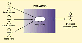
Let’s look at an example from a baseball ticket ordering system. A Kiosk Customer uses the computer system to order tickets, or a Phone Customer calls an 800 number for the ticket business and a Phone Clerk (an employee of the ticket business) uses the computer system to order tickets. Who are the actors? In a use-case diagram with a mixed-up system boundary, the modelers try to show both the users of the business and the users of the computer system in the same use-case model. The textual specification of the Order Tickets use case also becomes muddled: The set of interactions between the Phone Customer and the business is different from the set of interactions between the other actors and the computer system.
The undefined or inconsistent system boundary (Pitfall 1) is probably the most universal problem I’ve observed in projects trying use cases for the first time. When the system boundary is confused, it’s hard to know what’s in and what’s out. You can end up with:
- Too many use cases (Pitfall 4).
- Mixed up actor-to-use case relationships (Pitfall 5).
- Huge and confusing use-case specifications that try to address multiple levels of scope (Pitfalls 6 and 7).
- Use cases that can’t be finished because your team is trying to "boil the ocean" (Pitfall 10).
|
Mixed-Up Scope
|
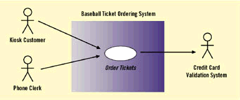
These problems can be avoided by being explicit about the scope and labeling the system boundary accordingly. For example, the system boundary could represent a computer system, with Kiosk Customer and Phone Clerk as actors who use the Order Tickets use case. Or, the system boundary could represent an entire enterprise. The actor, Phone Customer, is a user of the ticket business but not a user of the computer system. Both of these are legitimate models; the choice between them depends on whether you are trying to define the requirements of a computer system or employing use cases in business process modeling or re-engineering.
A related problem occurs when the system boundary is totally missing from the diagram. This problem often comes up when the use cases are modeled using a visual modeling tool (such as Rational Rose, the leading object-oriented modeling tool on the market) that doesn’t put the system boundary box on the use-case diagram.
If you are working with such a tool, you should still strive to make the system boundary explicit. Even if it’s not on the diagram, it should be in your head. Place the actors and the use cases on the diagram as if the (imaginary) box were there.
Use a standardized template for your use-case specifications. While the use-case diagram’s notation has been standardized as part of the Object Management Group’s Unified Modeling Language (UML), the natural-language use-case specification has not. To position your project for success in writing good use-case specifications, create a template for documenting them (preferably before you actually need to use it). The template provides consistency between use cases, and encourages adherence to project standards.
In the absence of an industry standard, various use-case specification templates have been proposed, with similar sets of fields. The Use Case Name is the name that appears under (or inside) the oval on the use case diagram. The Actor is the primary actor that initiates the use case. The Goal is a brief description of the use-case goal, from the perspective of the primary actor or actors. The Context is the background "story" in which the use case applies, while the Trigger is the specific event that causes the use case to start. The Normal Flow consists of numbered steps that describe the most typical sequence of interactions between the actor(s) and the system–what usually happens, including the Results. The Alternative Flows are alternate normal (success) paths, each described in terms of its trigger (what caused a jump from the normal flow), steps and result. Exception Flows are error paths, each described in terms of its trigger (what caused a jump from the normal flow), steps and result. An optional Issues field notes any requirements assumptions, upon which the use case is based. At the very least, a use case specification should answer these basic questions:
- Who? (the actors)
- Why? (the goal and/or context)
- When? (the triggering event)
- What? (the normal flow)
- What else? (alternative and/or exceptional flows)
In addition to the fields to be specified within each use case, it’s also helpful to define a standard for what information is to be specified for a group, or "package," of related use cases. This information should include a glossary of actor names and other important terms (preventing Pitfall 3), business rules that cross use cases, a "story" (or activity diagram) showing how the use cases relate over time, and so on.
For my company, I developed a Microsoft Word template file for specifying use-case packages, with customized styles for major elements and in-line guidance annotations. The customized styles are useful if you want to automate feeding the Word-based document into a requirements management tool. The built-in guidance is aimed at use-case writers who aren’t likely to go back and look at the project standards or course notes. It provides reminders on use-case naming conventions (e.g., short phrases beginning with an "action" verb), specification rules (e.g., use active subject-verb sentences; avoid branching logic) and helpful hints.
You don’t need to start designing a project use-case template from scratch; you can get examples from the web and tailor them. Alistair Cockburn has a web site (http://mem-bers.aol.com/acockburn/papers/OnUseCases.htm ) that provides a lot of helpful use-case resources, including a use-case template in HTML, MS Word and text formats.
|
Computer System Scope
Business Enterprise Scope
|
Point of View
Focus on goals. The thing that most visibly differentiates use case-based requirements from traditional functional system requirements (for example, "shalls") is the stick figure. It’s not the icon itself that is notable, but rather the emphasis on specifying the system from the perspective of its intended actors (human users and other external entities). In a use case-oriented view of the world, the system exists because the actors have some goals that are satisfied by using it. We write the use cases to specify the nature of the interactions between the actors and the system, resulting in the satisfaction of the actor’s goals. (Ivar Jacobson, father of use cases, used the term "results of value" to connote the importance of considering the actor’s real needs or goals in selecting use cases.)
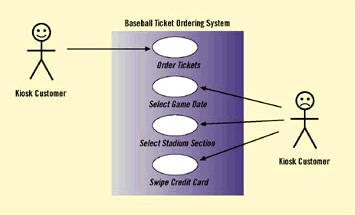
With that in mind, we should be able to glance at a use-case model and enumerate the things that the users want to do using the system. These things are not the user’s trivial interactions but real goals. Selecting use cases that reflect incidental actions, rather than real actor goals, results in too many use cases (Pitfall 4) and may cause a disconnect between the expression of the customer’s problem and the use case-based requirements (Pitfall 9).
So, to select good use cases, focus on those that reflect real goals of the actors. Then name the use cases from the perspective of the actor, not the system.
For example, Process Ticket Order and Display Schedule are things the system does, and so are not good use-case names (Pitfall 2). Order Tickets and View Schedule are goals of the system’s users (and thus good use-case names).
Another way that user goals get lost is, ironically, in the attempt by some modelers to make the use cases "object-oriented." The symptom of this situation is the existence of fat "CRUD" use cases that include all possible actions that might be performed on a business object. (The "CRUD" acronym stands for the ability to Create, Read, Update and Delete the object.) These use cases often have names that include the words "maintain," "manage" or "process."
What’s wrong with CRUD use cases? First and foremost, they often don’t relate directly to actor goals. They more often represent a union of various actor goals, from a variety of business contexts and processes, which have been grouped together because they share an object. What else is wrong with a CRUD use case? Its specification is typically long (Pitfall 6), it is often associated with too many different actors (Pitfall 5) and the "functional entitlement" of these actors to the entire use case is typically suspect (Pitfall 8; more on that later). In short, there are lots of times that we want to focus on objects when we are performing OO analysis, but the selection of use cases isn’t one of them.
Don’t confuse use-case specification with user-interface design. There’s a popular belief that, since use cases are concerned with actors interacting with the system, it would be a good idea to put pictures of all the user-interface screens in the use-case specifications. At first glance, the screen shots seem helpful, because they illustrate the actor/system interactions described in the specification.
However, the negatives far outweigh this benefit. If I wanted to be absolutely certain that I’d hit Pitfall 10 ("The use cases are never finished"), I would put screen shots in my use-case specifications. Here’s what I’ve observed on one project that did this: The use cases, which were intended to specify the system’s operational requirements, ended up including elements of the system’s user-interface design. At the point when the requirements needed to be approved and baselined, these design elements were, naturally, still being changed. So the customer couldn’t sign off on the requirements document, because it contained user-interface designs that were incomplete, incorrect and/or inconsistent.
Even if the use cases had been approved, it would have been a short-lived success. The user-interface design is likely to change over time. We don’t want the system requirements to be dependent on design. The dependency ought to go the other way–the user-interface design must satisfy the use-case requirements.
I’ve seen another problem in projects that put screen shots in the use cases. In attempting to make a one-to-one correspondence between use cases and screens, they selected use cases that reflected the chunks of user interface rather than user goals. (Typically, the user goal was "larger" than one screen’s worth of interactions.) They then tried to glue the various screen-based use cases into a complete user goal by using inter-use case relationships ("uses" or "extends"). This resulted in a spider’s web of relationships in the use-case model, which had more to do with screen navigation than user goals and functional entitlement. A screen navigation diagram is a useful piece of system documentation; however, it belongs in the user-interface (design) document, not the use-case (requirements) document.
A better approach is to loosely couple the user-interface details and use-case interactions. A little coupling is okay; including "low fidelity" pictures of the user interface can aid understanding of the use case. But don’t overly tie the fundamental interactions to the UI mechanisms, which are more likely to change. In the specifications, focus on the essentials of what the actor does (for example, "selects a game," "submits a request") rather than how the interaction is done (for example, "double-click on the Submit button").
One other, less obvious, problem that results from trying to make a correspondence between use cases and user-interface screens is the potential for incorrect functional entitlement (Pitfall 8).
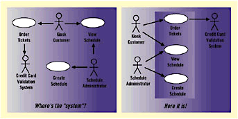
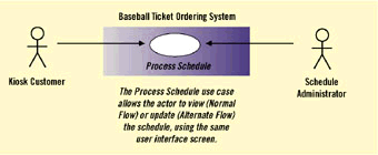
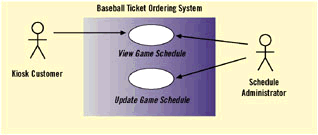
For example, let’s say that various users can use the Game Schedule screen to view the game schedule, but with proper authorization, a user (e.g., the Schedule Administrator) also can update the schedule using this screen. The modeler decides to combine the view and update functionality into a single Process Schedule use case, based on the common Game Schedule user interface screen.
This use case is associated with the actors that can only view the screen, as well as those who can also update it (perhaps this is an alternate flow). The result is incorrect functional entitlement. Just looking at the model, it appears that a Kiosk Customer can both view and update the schedule, just as the Schedule Administrator can. Splitting the use case, based on the actual user goals and functional entitlement, rather than grouping based on user interface, results in a correct model.
|
Formatting
|
|
Goals vs. Incidental Actions
|
Regular Inspection
Review your use-case diagrams and specifications. If you can’t prevent all pitfalls, you can at least catch the problems as early as possible and fix them. This idea isn’t something new and sexy. The classic approach to code inspections has been around for 25 years, and the application of a peer review process is a Key Process Area for the Capability Maturity Model’s Level Three.
How does this apply to use cases? Projects in our company have had good results with a multiple-pass review process. First, the use-case diagram is reviewed, with simple "stubs" for the use-case specifications (just the use-case name and goal or brief description).
This review is performed as early as possible on a draft version of the diagram, before detailed use-case specifications are written. Following the draft-diagram review, the diagram is corrected, and the detailed specifications of the use cases are completed. Then a formal review of the final diagram, with the specifications, is performed.
We have found that this two-phase review process is better than a single "Big Bang" review. Substantive organizational problems with the use-case diagram are identified before much time is invested in writing detailed specifications. This approach reduces the amount of rework that needs to be done when the diagram requires reorganization.
Other tips for effective use-case reviews:
- Use a review checklist to help detect common use-case problems.
- Present the material to "tell a story." Sometimes presenting graphical material, rather than linear text, is challenging. We suggest a breadth-first overview, followed by an in-depth examination of small groups of related use cases. For instance, the presenter might cover the part of the use-case diagram that is related to one actor or to a particular business process, then go through those specifications in detail. The review then returns to the diagram to consider another related set of use cases. Never use alphabetical order as a presentation strategy! (Yes, I really have seen this.)
- Consider non-traditional review techniques for the initial model review. I like to use the "Yellow Sticky Wall Review" (the name was coined several years ago at the IBM Object Technology University) for informal reviews of graphical models. The diagrams are printed and posted on the walls of the review location. The reviewers write their comments on yellow sticky notes and place them on the diagram near the appropriate part of the model.
|
Confusing Functional Entitlements
Correct Functional Entitlements
|
Common Errors
The pitfalls I’ve described are not an indictment of use cases; rather, they are are representative of the difficulties in their application encountered by practitioners who have never used them before–and most use-case development teams do include inexperienced members.
Moreover, the customers, end users and domain experts who participate in requirements workshops generally have no prior experience with use cases. Because of the simplicity of the modeling notation and the natural-language specifications, it’s easy to get started with use cases.
However, the simplicity of the format should not disguise the fact that requirements analysis and specification is not a trivial pursuit. Many teams encounter similar pitfalls in their first attempts to work with use cases.
These suggestions can help your team avoid some of these problems.





相关推荐
在进行用例分析时,如何避免陷入常见的陷阱是软件开发中的关键问题。用例作为一种记录系统和软件需求的流行技术,其简洁的图形表示和易理解的自然语言规范深受开发团队喜爱。然而,这种简单性也可能导致误解,尤其是...
Learn how to avoid falling into common pitfalls. Learn how to use C to workaround some Objective-C limitations. Who this book is for iOS and OS X developers who need to troubleshoot problems and ...
The other topics covered here are how to share data between containers, the common use cases, and the typical pitfalls to avoid. [2 ] Preface Chapter 8, Orchestrating Containers, explains how to ...
Explore the different types that Swift offers and what pitfalls to avoid Error handling with do-try-catch block Delve into Generics and Generic programming Implement several design patterns in a ...
This book uses a hands-on approach by providing case studies from each of these domains: you’ll see examples that demonstrate how to use machine learning as a tool for business enhancement....
How can we use a class Foo in a header file without access to its definition? We can declare data members of type Foo* or Foo&. We can declare (but not define) functions with arguments, and/or ...
- **Common Pitfalls**: Common issues encountered when working with model binding, along with strategies to avoid them. - **Best Practices**: Recommendations for effective use of model binding to ...
He also mentions many of the pitfalls to look out for when programming across different UNIX system implementations and points out how to avoid these pitfalls using relevant standards such as POSIX ...
He also mentions many of the pitfalls to look out for when programming across different UNIX system implementations and points out how to avoid these pitfalls using relevant standards such as POSIX ...
He also mentions many of the pitfalls to look out for when programming across different UNIX system implementations and points out how to avoid these pitfalls using relevant standards such as POSIX ...