- 浏览: 4762062 次
- 性别:

- 来自: 济南
-

最新评论
-
wahahachuang8:
GoEasy 实时推送支持IE6-IE11及大多数主流浏览器的 ...
服务器推送技术 -
pdztop:
inffas32.asm(594) inffas32.asm( ...
zlib 在 Visual Studio 2005 下编译失败的解决办法 -
myangle89:
这个方法有效果,但还是绕了一大圈。另外:如果每次这样使用,会造 ...
利用 Spring 与 Log4J 巧妙地进行动态日志配置切换并立即生效 -
lsw521314:
亲,请把用到的包贴出来好么?这版本问题搞得我头大······· ...
lucene MMAnalyzer 实现中文分词 -
guji528:
多命令执行:cmd /k reg delete "H ...
REG Command in Windows XP - Windows XP REG命令的作用和用法
1-2. UML and UML tools
When you draw UML, do you draw it by hand or do you use a tool? Experience the advantages of using a tool. Why a tool? Here are just a few of the many advantages :
- Allows you to draw clean diagrams
- It draws elements in their appropriate sizes
- It is easy to share or exchange UML models with other people
- You can use Undo/Redo over and over to try and figure out what you really want
- It gives you an alert when you draw diagrams against the UML specification
- Data can be inputted in several ways (Graphs, tree structures..etc)
- Data is easily reusable
- You can manage all data and references between them
If you are a beginner in UML, you will find that #4 and #5 very helpful for you. Because mistakes can easily be "Undone" so you can make the perfect UML diagrams. Also, when you are creating an abstract class out of a class, the abstract class name will be automatically shown in Italic as the way it is supposed to be in the specification. There is so much more that you can get an advantage of by using JUDE to draw UMLs. JUDE will become your UML tutor. Just try playing around with it. And remember, if you ever make a mistake, you can always do "Undo" it and try again.
1-3. Description of JUDE
There are many UML tools that you can use these days. The one I prefer is "JUDE/Community" (JUDE stands for java and UML Developer's Environment). I am a little bias, I am a member of JUDE Development Team and have been developing and perfecting JUDE over the years. I want more people to try JUDE and learn to love it like I do.
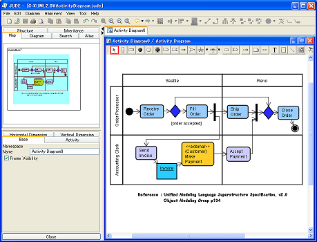
There are two versions of JUDE; JUDE/Community (Free version) and JUDE/Professional (Product version). JUDE has following features :
- JUDE/Community supports all basic UML 1.4 diagrams
- JUDE/Professional supports all basic UML 1.4 diagrams, some UML 2.0 specifications and Entity-Relationship diagrams (ER diagrams are supported since JUDE/Professional ver 3.2)
- Unlimited UNDO/REDO feature
- Drag scrolling, changing view freely using "Map View" to make it easy to edit large scale of diagrams
- Import and export of java source files
- Automatic generation of class diagrams with model information
For more information about features of JUDE, please check out JUDE/Community page .
1-4. Installation of JUDE
Now let's install JUDE. You will need to first install java Environment to run JUDE, so install java Environment. It is very easy to install both of them.
1-4-1 System Requirement
| Windows 2000, XP, Vista |
| Pentium III 600MHz or higher |
| 256MB or more |
|
Sun Microsystems J2SE 1.4.1_07 or later OR J2SE 1.4.2_05 or later OR JDK5.0 (JDK 5.0 is supported since JUDE/Community 3.1) |
JUDE works on J2SE Environment such as Windows98, Linux and MacOS. However we have not tested them enough to support those environments officially. So I recommend installing JUDE on WIndows. If you need information about how to set up on other environments except Windows, please refer to this FAQ
1-4-2 Install java Environment
If you already have installed required version of java environment on your machine, skip this step and go next. If you haven't, please go on Sun Microsystems page and install java Environment by following procedure on its page. Please read following notes before you install java environment.
- Please make sure to install required version of java environment. JUDE might not work properly on non-supported versions of java.
- Please make sure that J2RE is included when you install J2SE. (JUDE would use J2RE by default that is installed into OS)
1-4-3 Download JUDE
Next download JUDE From Download page .
Select the latest version of jude-community-x_x-setup.exe (approximately 5MB) and download it. (By the way, I used JUDE/Community 3.2 to write this article.)
1-4-4 Install JUDE
After the download finnishes, double click on the file to start installing JUDE. After double clicking on it, the installer wizard will launch and all you have to do is to specify the place to install it.
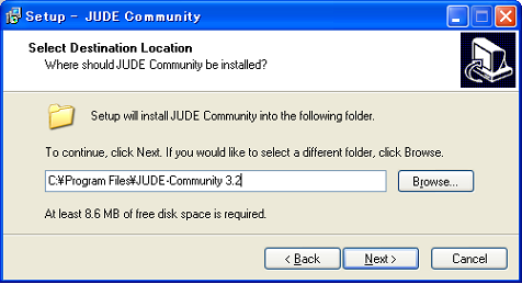
If you are on Windows98 orME, you will have to open the file called jude.bat with an editor then set the absolute path of the folder in JUDE/HOME variables. The jude.bat file is located in JUDE install folder.
1-4-5 Run JUDE
Launch JUDE from Windows Start Menu. This image will be shown when you start JUDE.
(The image of JUDE starting)
1-5. Fundamental Components and Basic Operation of JUDE
Now I will show you screen contents of JUDE and guide you some basic operations.
1-5-1 Fundamental Components
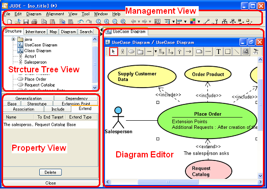
- Management View
The management View has the Main Menu that includes functions related to the whole project, such as file operation and editing and the Tool Bar for frequently used functions. - Diagram Editor
The Diagram Editor is used to edit diagrams and models. You are able to open multiple diagrams at the same time. - Structure Tree
It displays models in a tree structure. You can carry out various operations using the Pop-Up menu of model elements on here. - Inheritance Tree
The Inheritance Tree View displays models in a tree structure based on the inheritance relationships between classes. - Map View
The Map View provides an overview of the diagram that is opened in the Diagram Editor. The area displayed in the Diagram Editor can be specified by a right-drag and the diagram in the Diagram Editor can be scrolled by a left-drag. This function is very useful for big diagrams especially. - Property View
The Property View is used to display and edit the properties of model elements.
1-5-2 Create a new project
In JUDE, UML data will be saved as (Name).jude. These files are called project files. There is no project opened when launching JUDE ata the first time. Okay, now let's create a new project. Select [File] - [New] from Main Menu. The Structure Tree and Property View will be displayed once you create a new file.
Default Project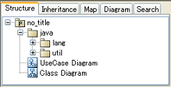
"UseCase diagram" and "Class diagram" are created in a new project with "no_title". "no title" package is associated with java default package. However we are not going to use an Export java feature in this tutorial, so let's carry on. java package is associated with java platform API and it holds basic classes such as "String" and "Vector"..etc. These classes can be used as types of Attributes.
1-5-3 Create Packages and Diagrams
To create a new package, Pop-Up menu in the Structure Tree is mostly used. To create a new diagram, select [Create Diagram] from Pop-Up menu in the Structure Tree or select from [Diagram] in Main Menu.
Diagrams that you can create with JUDE/Community(3.2) are :
- Class diagram
- UseCase diagram
- Statechart diagram
- Activity diagram
- Sequence diagram
- Collaboration diagram
- Component diagram
- Deployment diagram
-
Object, Package, Robustness diagrams are also supported.
1-5-4 How to create and edit items
The basic operation to draw diagrams with a tool is almost the same in general drawing tools. If you have never used drawing software and have no experience with them, you will have to get used to it, so let's get it started.
1-6 UML about Bowling
Now all is set up and we area ready to draw diagrams. What diagrams should we draw? Have you gone bowling lately? I myself enjoy the bowling competition our company held the other day. I guess the most people have bowled. So let's use the bowling for the subject for UML this time. Let's draw UML of the system to show the bowling scores.
Bowling Score
Here are the requests.
- Show the track of a bowling score once the game has started.
- Update the score every time the player throws the bowl.
- Players can change the scores during the game.
- Show an animation when someone made the strike.
Our purpose here is to try experiencing UML using UML modeling tool. It is not important to draw the perfect diagrams. Then let's get it started. Are you ready?
1-7 Draw a UseCase diagram
Now let's start drawing diagrams, we are going to start with a UseCase diagram. We are going to draw a diagram like this figure below.
UseCase diagram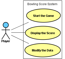
Open a UseCase diagram that comes with the default project file. Right-click on the UseCase diagram in the Structure View then select [Open Diagram] in Pop-Up menu or double-click on it to open UseCase diagram in the Diagram Editor.
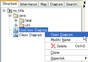
In the Diagram Editor, there is a Tool Palette with buttons to edit diagrams.

Place the mouse pointer over the button if you want to know what the button is for, a Tooltip will show the description of the button. On the Diagram Editor, you will draw diagrams switching modes with using these buttons. For example when you move elements on the Diagram Editor, turn the [select mode] on then select the elements you want to move then you can move them. If you want to create the certain element continuously, switch the mode to [Lock Selected Mode]...etc.

|
Select Mode. During this mode is on, you can select, edit, move and change size of items. |

|
Lock Selected Mode. It enables you to craete the selected element continuously. For example if you create an Actor without the Lock Select Mode on, once you add an Actor on the Diagram Editor, you will have to select the Actor again to create another Actor. However with the Lock Select Mode on, the focus stays on Actor and you can create more than one Actor continuously without selecting an Actor again on the tool palette. |

|
Set Relation End to the center of the item. It places the ends of lines. (e.g. Associations, Generalizations, or Dependencies) at the center of Model Elements. |
Select an Actor button on tool palatte, then click on anywhere in the Diagram Editor to create one. Enter "Player" for the name of this Actor.
Now let's create three UseCases just like the way you created the Actor.
You can move elements by dragging them, and when you want to rename them, just double-click on the name of the elements.
Now let's draw a line between the Actor and three UseCases. Each line has its own meanings. Now what we need here is a line called Association. Select an Association button on tool palette. To create an Association, you have to click twice, first click on the begenning target and another on the end target. First, click on the "Player" Actor, then click on the "Start the Game" UseCase. Now an association line is drawn between the "Player" Actor and "Start the Game" UseCase. Then create two more associations just like you did. Now add a rectangle and put a text "Bowling Score System" in it to complete the diagram!
Tips: Cancellation during making associationsIf you clicked on the wrong target by mistake while you were going to draw an association line, press [ESC] key or right-click to redo it. It works for any lines between two elements such as : Generalizations, Realizations and Dependencies. You might have noticed that UseCases and an Actor were added in the Structure Tree when you created them in the Diagram Editor. Also the properties of the items that are selected in either the Diagram Editor or the Structure Tree are shown in the bottom left pane called Property View. You can modify data in several fields; in the Diagram Editor, Structure Tree, Property View where ever it works the best for you depending on case. Let's use the Property View and change the name of this UseCase diagram. Select the "UseCase Diagram" in the Structure Tree, so the property of the UseCase diagram will be shown in the Property View. The name it to "Bowling UseCase Diagram" and press [Enter] key to complete. |
Tips: Deleting elementsTo delete Actors or UseCases, select [Delete from Model] or [Delete from Diagram] from their Pop-Up menu. The reason that there are two ways to delete elements is because elements like Actors and UseCases can be shared with other diagrams and also used in other diagrams.
|
Tips: Zooming and ScrollingI will introduce you to features JUDE used for viewing operations. The UseCase diagram we just drew was small scale so there was no need to used the feature for the view. Although when you handle large-scale diagrams, you will have ato focus on some parts of the diagram to modify it. And JUDE has a feature that makes the operation very easy. The displayed area can be specified by a right-drag in the Diagram Editor in JUDE. It enables you to move the diagram diagonally. To zoom in or zoom out, select [View] menu from Main Menu or use the Tool bar. Also to specify the area to display you want to see, you can use Map View in the Project View. (The top left pane). |
Tips: Undo and RedoJUDE has conservative Undo and Redo features lets you revert back 100 times! If you have not used Undo so far, try and see how it works! So there is no need to worry about making mistakes at all when drawing diagrams. What a relief! |
1-8 Draw an Activity Diagram
Now let's focus on the "Display the Score" UseCase and draw the flow of it on an Activity diagram. First, you have to add an Activity diagram to your project file. Select the UseCase of "Displaya the Score" then select [Create Diagram] - [Add Activity Diagram] on its Pop-Up menu. A new Activity diagram will be added and opened in the Diagram Editor.
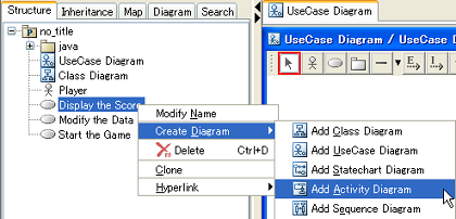
Name the Activity diagram "Behavior of displaying Scores" just how you changed the name of UseCase diagram.
Activity diagarm has following buttons in its Tool bar.

Now let's draw an Activity diagram just this below figure.
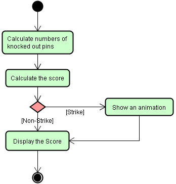
Activity diagrams are very similar to FlowChart diagrams
and they describe how things flow and connect to next
actions.
In this Activity diagram, it describes how things go
and act after the player throws a ball and how the score
gets displayed after that. From this Activity diagram,
you can get the information that an animation will be
shown when someone made a strike.
Let's start creating all elements except arrows. You can create them the same way you created an Actor and UseCases. Just select elements you want to add from the tool palette then drop them on the Diagram Editor. You can edit the EntryAction that is an action to set in ActionState in either the Diagram Editor or the Property View.
Resize
The text of "Calculate numbers of knocked out pins" is rather long to have it all in one line inside the ActionState. So let's change the size of this ActionState and also let this name line break down. To change the size of elements, select one of corners of the element and drag it.
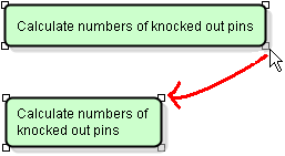
Now let's add arrows between elements to show the flow of these action objects. This arrow is called Transition. To draw a Transition, you will have to click two targets to connect as how you did to draw Association lines in the UseCase diagram, but you have to be careful because the arrow is created by the order you click. I will show you how to create Transitions continuously.
Tips: How to create items continuously
So how are you doing so far?
Could you create items continuously? [Strike] is a guard of Transition. So click on the Transition arrow then enter "Strike" in Guard column in the Property View. 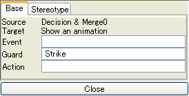
I will introduce three tips for how to make clean diagrams. |
Tips: Multiple selectionThere are three ways to select multiple items on the Diagram Editor.
|
Tips: AlignmentElements can be aligned in horizontally and vertically in JUDE. Let's use [Align vertical center] for items on the left (All items except "Show an animation"). It will make the diagram look tidy. Draw a rectangle including all left target items inside of it to select them. Then select [Alignment] - [Align Vertically] - [Align Vertical Center] from Main Menu or you could do it by selecting the icon on Tool Bar down below the Main Menu. |
Tips: Line StylesThere are two types of lines in JUDE.
The default of line style is set to [Normal Line Stile]. However [Right Angle Line Style] can look good sometimes. So why don't we use [Right Angle Line Style] for this Activity diagram. Select all lines then select [Line Style] - [Normal] on its Pop-Up Menu or select the icon on Tool Bar. 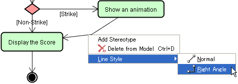
|
1-9 Draw a Class Diagram
Now we are going to draw a Class diagram. Class diagrams and Sequence diagrams are frequently used diagrams in UML, so we are going to take much more time here than other diagrams we have drawn.
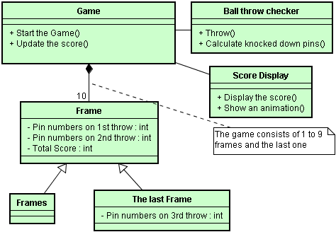
This Class diagram is an analytic diagram focused on Bowling Game and its scores. This Class diagram describes that a bowling game consists of a sequence of ten frames and each frame consistes two throws except the last frame that consists three throws. First, change the name of the default Class diagram to "Analysis Class diagram".
There are below buttons in Class diagram's tool palatte.

Well, let's start drawing the outline first, then do details later. Create six classes. You can create them just how you created an Actor and UseCases.
The arrows that are coming from the bottom two classes are called "Generalization". When creating Generalizations, click on the start target first.
All relationship in the above Class diagram figure that we are going to draw except Generations and the dotted line are called Associations that you have already drawn in UseCase diagram. Let's draw these Association lines now. The type of Association between "Game" class and "Frame" class are called "Composition". With this composition association, this means that the game consists of the frames and if there were no frames, there will be no game.
How to set the Property of Association
Association has several properties to set such as Aggregation, Composition, Multiplicity..etc. In this case, you need to set the Composition to the Game class.
- Method 1 : Use Dropdown list of Association on Tool palette
- Method 2 : Set it on the Pop-up menu of the Association
- Method 3 : Set it on the Property View of the Association
At this time, why don't you set the Composition with Method 2, from the Pop-up menu.
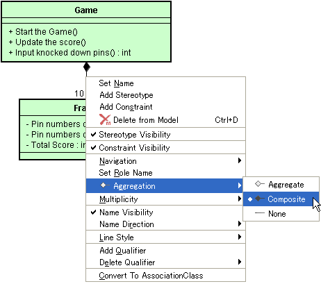
Even though you select the same association to open a Pop-up menu of it, you could get different menus in the Pop-up menu depending on where you click on it. Try to click on the association line where it is closed to the Game class. Then you can set the property for the Game class.
Now let's set the Multiplicity from the Property View. When selecting the Association in the Diagram Editor, the property of the Association will be shown in the Property View (See the below figure) then you can modify the Multiplicity.
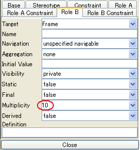
You have to be careful when you set the multiplicity because there are two role tabs shown for two different targets of the association. So make sure that you have chosen the right one. In this case, choose the tab that has "Frame" for Traget, then set the multiplicity to 10.
Now we are going to add Attributes and Operations to the classes.
Add Attributes to Classes
Now we are going to add three Attributes to the "Frame" Class. There are three ways to do that.
- Method 1 : Using the Pop-up menu on the Diagram Editor
- Method 2 : Using the Pop-Up menu in the Project View.
- Method 3 : Using the Property View of the class
Select the "Frame" class on the Diagram Editor and select [Add Attribute] on its Pop-up menu. Then type "Pin numbers on 1st throw" as the Attribute name. Then add more other attributes. You should try adding them using other two methods shown above for practice. If you want to delete attributes, you can delete them from the Property View or the Structure Tree. The default of Visibility is private, and the default of Type is set to void. To change those default setting, use the Property View. Also Attributes can be added by using Shortcut Key "Ctrl + F". (Shortcut key for adding operations is Ctrl + M).
Add Operations to Classes
You can add and edit Operations to class just exact the same way how you do to Attributes. Why don't you add Operations to classes from the Property View.
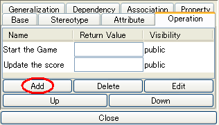
To add Operations on the Property View, press [Add] button. To edit information of added operations, use this property view or select added operation and press [Edit] button to have more detailed property view. You can edit all detailed information such as Parameters in this Operation Property dialog. Press [Delete] button when you want to delete the selected operation. [Edit] button is for when you want to open an Operation Propety Dialog. [Up] and [Down] buttons will rearrange the order of operations. Okay, after you completed adding the operations of "Calculate knocked down pins", add a parameter "Pin numbers : int" using the Operation Property.
How are you doing so far? The main purpose of all of this is drawing UML diagrams using JUDE, so do not worry about technical details and just keep moving on.
1-10 Draw a Sequence diagram
Now we are going to draw a Sequence diagram that displays the time sequence of the "Calculate knocked down pin numbers" object that Game class consists. Sequence diagrams can be added under the UseCase or Operations in the Structure Tree. Select the Operation of "Calculate knocked down pin numbers" then select [Add Sequence diagram] on its Pop-up menu.
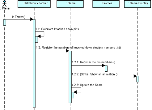
This diagram describes the time sequence of each actions that are participated in the interaction that when "Player" throws the ball, "Ball Throw Checker" object recognizes it then registers the numbers of knocked down pins to "Game" object, then if it was a strike , the "Display the Score" object shows an animation. We have drawn an Activity diagram just looks like this but there is a diffrence. In Sequence diagrams, it displays those in the time sequence and consists of the vertical dimension (time) and horizontal dimension (different objects.).
Sequence Diagram's Toolpalatte
These buttons on Tool Palette in Sequence diagram look a bit different compared to other buttons we have seen in other diagrams. So its different to operate elements too than we have done in other diagrams.
First, create five objects you see on the top. But don't rush it out. Because I want to tell you something. We can create objects by choosing the object buttons from the Tool palette just like we always have done but there is much convenient way to create these objects in Sequence diagram. Use the Structure Tree! This is how you do it. Select the base class in the Structure Tree then drag and drop it onto the Sequence diagram in the Diagram Editor.
Creating Objects by dragging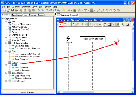
You can also select multiple classes in the Structure Tree then drag them and drop onto Diagram Editor at once.
Now we are going to create messages. The message from "Player" to "Ball Throw Checker" object is an asynchronous message. Select the forth button from the left on the Tool Palette. Then click on the lifeline of "Player" and click on "Ball Checker" the next, the message is drawn! Now double click on the name message0 and change it to "Throw". Now create a message "1.1 Count number of knocked down pins" just like how you just made the "Throw" message. After you finish, let's create a Synchronous message that is send out from the "Ball Throw Checker" sending it to itself. (It is called a SelfMessage). Select the third button from the left on Tool Palette. When you created an asynchronous message, you clicked on Lifelines. But click on the Activations when you create Synchronous messages.
Creating a Selfmessage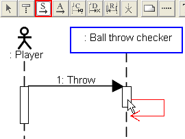
Relating Operations to Messages
Messages can be related to the operations. For example, when an Operation's name has changed in Class diagram, the message can be changed to the same automatically if the operation was related to the message. To make a relation between operations and messages, go to the Property view while selecting the Message then set the Operation in Operation column. So now make a relation between "Calculate numbers of knocked out pins" message and the operation you jsut created.
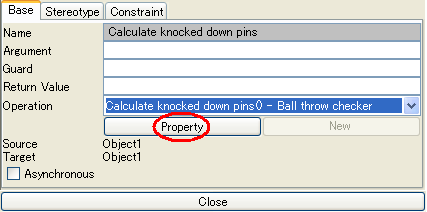
If some operations have been already related to the "Ball Throw Checker" Class which is a base class of the message sender, those operations will be shown in the Operation column. If there is no operation related yet to any messages, you can add a target operations by pressing [New] in the Property View. Pressing [Property] button will show you the property of selected operation, so you can change the name of parameters of it. You don't have to have operations related to messages always, however just keep it in your head that it makes it easier to keep the compliance with other diagrams if you have made relations between operations and messages.
Now, create other messages.
Tips: Activation SizeYou might have noticed that he size of Activations get longer every time the new messages are added or get moved. It is because that the source activation needs to be longer than target activatins that receive messages from the source activation in UML specification. So JUDE automatically adjusts it every time you make new messages. JUDE does adjust the size of Activations to make them grow but doesn't make them shorter. You can make them shorter by yourself if you want to. You can change the size of Activations with the same way you resized the ActionState in Activity diagrams. Select the Activation then drag the little box shown on the corner to resize it. It works for all activations of messages except for Asynchronous ones. |
1-11 Other Diagrams
Here are figures of Collaboration diagram and StateChart diagram of Bowling.
Collaboration Diagram
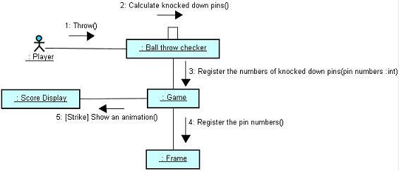
This Collaboration diagram expresses the mutual action that you drew on Sequence diagram.
Collaboration Tool palatte

Click on the link when creating messages.
StateChart Diagram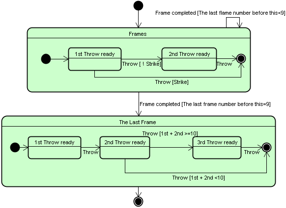
This StateChart diagram is drawn the Chart of how the game goes.
StateChart Tool palatte
1-12 Features of JUDE
JUDE has much more features that is not introduced on this page. Try these following features.
- Export of java Shelton Code
- Import of java Source Files
- Template Generation of java Source Files
- Model replacement by dragging in Structure Tree
- Icon Notation of Boundary、Control、Entity Classes
- Set the default color for items
- Set the default color for stereotypes
It is possible in JUDE System Properties. - Changing the Associatio targets by draggin the corner
of Association lines
Just by dragging the line end to other items, you can change the targets. - Paste images on Microsoft Office(Rasta)
- Import JUDE Model


相关推荐
"Learn UML with JUDE(二).doc"可能进一步深入到UML的其他图表类型,比如序列图和协作图的创建,以及如何在JUDE中表达对象间的交互。同时,可能还会介绍如何利用JUDE进行模型验证和检查,确保设计的准确性。 "Learn...
### UML与JUDE:专业建模工具的探索 #### 概览 UML(统一建模语言)是一种广泛使用的标准建模语言,用于软件系统的设计和文档化。它提供了一种图形化的表示方法,使得系统架构师、开发者和业务分析师能够共同理解...
### UML与JUDE学习指南 #### 一、概述 本文旨在介绍如何使用JUDE这一工具来学习和绘制UML(统一建模语言)。UML是一种广泛应用于软件工程领域的标准化图形化语言,用于描述软件系统的设计和架构。通过JUDE这款强大...
在这种情况下,"绿色版的UML工具JUDE-Community"就成为了一个理想的选择。 JUDE-Community是一款免费的开源UML建模工具,特别适合个人用户和小型团队进行软件建模工作。它提供了基本的UML图表绘制功能,包括类图、...
### Lean UML with JUDE #### 概述 本文档旨在为初学者提供学习使用免费UML建模工具JUDE/Community的方法。通过实际操作来加深对UML的理解和掌握,帮助读者学会如何使用JUDE进行建模。 #### UML与UML工具 在绘制...
《使用JUDE学习UML:从入门到精通》 UML(统一建模语言)是一种通用的建模语言,用于软件开发中的需求分析、设计和文档化。它提供了多种图表,如用例图、活动图、类图和序列图等,以帮助我们可视化和理解复杂的系统...
《UML画图工具Jude 5.5详解与应用》 UML(Unified Modeling Language),统一建模语言,是软件开发过程中一种重要的图形表示工具,用于可视化、构造和文档化系统模型。Jude 5.5是一款轻量级的UML画图工具,它以其...
**UML制作工具JUDE详解** UML(Unified Modeling Language),统一建模语言,是软件工程领域一种广泛使用的建模工具,它提供了一种图形化的表示方式来描述软件系统的设计、架构和行为。JUDE(Java Use Case Diagram...
《Jude:便捷的Java UML设计工具》 在软件开发过程中,UML(统一建模语言)是一种广泛使用的建模工具,它可以帮助开发者清晰地表达系统设计和架构。对于Java开发者来说,Jude是一款非常实用的UML设计工具,尤其适合...
《使用Jude绘制UML图:轻量级的高效工具》 在软件开发过程中,UML(统一建模语言)图是一种重要的可视化工具,它帮助开发者清晰地表达系统设计、需求分析以及各种软件元素之间的关系。Jude,作为一款专为UML设计的...
《UML工具Jude5详解及其免费版安装指南》 UML(统一建模语言)是一种在软件开发过程中广泛使用的标准化建模语言,它能够帮助开发者以图形化的方式描绘出系统的结构和行为,提高设计质量和沟通效率。在这个领域中,...
**UML建模工具Jude 5.4详解** UML(统一建模语言)是软件工程领域一种广泛使用的建模工具,它提供了一种图形化的语言,用于描绘软件系统的设计、结构和行为。Jude是一款高效且易用的UML建模工具,特别适合于快速...
JUDE 使用教程(UML画图工具之一) JUDE 是一款功能强大且实用的 UML 绘图工具,通过本教程,您将学习如何安装、使用和掌握 JUDE 的基本功能,并学习如何使用 JUDE 创建 UML 图。 JUDE 安装教程 为了使用 JUDE,...
2. **全面的UML支持**:JUDE支持多种UML图表类型,包括用例图、类图、对象图、组件图、部署图、协作图、顺序图、状态图和活动图等,覆盖了软件开发中的多个阶段和视角。 3. **模型驱动开发(MDD)**:JUDE支持模型...
**UML作图工具JUDE软件** 在IT行业中,统一建模语言(Unified Modeling Language,简称UML)是一种标准化的图形表示法,用于软件工程领域,帮助开发者、分析师和项目团队成员清晰地表达和交流系统设计。UML提供了一...
### UML2.0 for JUDE3:深入解析与应用指南 #### 一、概述:JUDE与UML的结合艺术 JUDE3作为一款强大的UML建模工具,不仅支持从安装到实际建模的全过程,更特别之处在于其对UML2.0标准的支持,为用户提供了更为先进...
JUDE(Java and UML Developers' Environment),一个小巧实用的UML建模软件,绝对可以符合UML建模的要求,JUDE是一个中日合作采用XP开发方式纯JAVA开发的软件,也可以说是半个国产软件,但这绝对不是我推荐这款软件的...
《UML建模工具Jude 5.5.2 使用手册》是一份详细指南,旨在帮助用户掌握如何利用开源轻量级工具Jude绘制统一建模语言(UML)的各种图表。本文档不仅介绍了Jude的基本特性,还通过实例演示了如何绘制包括用例图、活动...
Jude建模工具是一款专为软件开发者设计的强大UML(统一建模语言)工具,它在软件工程领域中扮演着至关重要的角色。UML是一种标准的建模语言,用于可视化、构建和文档化软件系统的设计。通过使用Jude,开发团队能够更...
Jude是一款很好的UML工具,JUDE(Java and UML Developers' Environment),一个小巧实用的UML建模软件,不到2M,绝对可以符合UML建模的要求,可以画CLASS,USECASE,STATECHART,ACTIVITY,OBJECT,SEQUENCE,...