OpenGL ES Tutorial for Android
– Part I
I'm going to write a couple of tutorials on using OpenGL ES on Android phones. The theory of OpenGL ES is the same on different devices so it should be quite easy to convert them to another platform.
I can't always remember where I found particular info so I might not always be able to give you the right reference. If you feel that I have borrowed stuff from you but have forgotten to add you as a reference, please e-mail me.
In the code examples I will have two different links for each function. The actual function will be linked to the android documentation and after that I will also link the OpenGL documentations. Like this:
gl.glClearColor(0.0f, 0.0f, 0.0f, 0.5f); // OpenGL docs.
So, let's start.
In this tutorial I will show you how to set up your OpenGL ES view that’s always a good place to start.
Setting up an OpenGL ES View
Setting up a OpenGL view has never been hard and on Android it is still easy. There really are only two things you need to get started.
GLSurfaceView
GLSurfaceView is a API class in Android 1.5 that helps you write OpenGL ES applications.
· Providing the glue code to connect OpenGL ES to the View system.
· Providing the glue code to make OpenGL ES work with the Activity life-cycle.
· Making it easy to choose an appropriate frame buffer pixel format.
· Creating and managing a separate rendering thread to enable smooth animation.
· Providing easy-to-use debugging tools for tracing OpenGL ES API calls and checking for errors.
If you want to get going fast with your OpenGL ES application this is where you should start.
The only function you need to call on is:
public void setRenderer(GLSurfaceView.Renderer renderer)
Read more at: GLSurfaceView
GLSurfaceView.Renderer
GLSurfaceView.Renderer is a generic render interface. In your implementation of this renderer you should put all your calls to render a frame.
There are three functions to implement:
// Called when the surface is created or recreated.
public void onSurfaceCreated(GL10 gl, EGLConfig config)
// Called to draw the current frame.
public void onDrawFrame(GL10 gl)
// Called when the surface changed size.
public void onSurfaceChanged(GL10 gl, int width, int height)
onSurfaceCreated
Here it's a good thing to setup things that you don't change so often in the rendering cycle. Stuff like what color to clear the screen with, enabling z-buffer and so on.
onDrawFrame
Here is where the actual drawing take place.
onSurfaceChanged
If your device supports flipping between landscape and portrait you will get a call to this function when it happens. What you do here is setting upp the new ratio.
Read more at: GLSurfaceView.Renderer
Putting it together
First we create our activity, we keep it clean and simple.
package se.jayway.opengl.tutorial;
import android.app.Activity;
import android.opengl.GLSurfaceView;
import android.os.Bundle;
public class TutorialPartI extends Activity {
/** Called when the activity is first created. */
@Override
public void onCreate(Bundle savedInstanceState) {
super.onCreate(savedInstanceState);
GLSurfaceView view = new GLSurfaceView(this);
view.setRenderer(new OpenGLRenderer());
setContentView(view);
}
}
Our renderer takes little bit more work to setup, look at it and I will explain the code a bit more.
package se.jayway.opengl.tutorial;
import javax.microedition.khronos.egl.EGLConfig;
import javax.microedition.khronos.opengles.GL10;
import android.opengl.GLU;
import android.opengl.GLSurfaceView.Renderer;
public class OpenGLRenderer implements Renderer {
/*
* (non-Javadoc)
*
* @see
* android.opengl.GLSurfaceView.Renderer#onSurfaceCreated(javax.
* microedition.khronos.opengles.GL10, javax.microedition.khronos.
* egl.EGLConfig)
*/
public void onSurfaceCreated(GL10 gl, EGLConfig config) {
// Set the background color to black ( rgba ).
gl.glClearColor(0.0f, 0.0f, 0.0f, 0.5f); // OpenGL docs.
// Enable Smooth Shading, default not really needed.
gl.glShadeModel(GL10.GL_SMOOTH);// OpenGL docs.
// Depth buffer setup.
gl.glClearDepthf(1.0f);// OpenGL docs.
// Enables depth testing.
gl.glEnable(GL10.GL_DEPTH_TEST);// OpenGL docs.
// The type of depth testing to do.
gl.glDepthFunc(GL10.GL_LEQUAL);// OpenGL docs.
// Really nice perspective calculations.
gl.glHint(GL10.GL_PERSPECTIVE_CORRECTION_HINT, // OpenGL docs.
GL10.GL_NICEST);
}
/*
* (non-Javadoc)
*
* @see
* android.opengl.GLSurfaceView.Renderer#onDrawFrame(javax.
* microedition.khronos.opengles.GL10)
*/
public void onDrawFrame(GL10 gl) {
// Clears the screen and depth buffer.
gl.glClear(GL10.GL_COLOR_BUFFER_BIT | // OpenGL docs.
GL10.GL_DEPTH_BUFFER_BIT);
}
/*
* (non-Javadoc)
*
* @see
* android.opengl.GLSurfaceView.Renderer#onSurfaceChanged(javax.
* microedition.khronos.opengles.GL10, int, int)
*/
public void onSurfaceChanged(GL10 gl, int width, int height) {
// Sets the current view port to the new size.
gl.glViewport(0, 0, width, height);// OpenGL docs.
// Select the projection matrix
gl.glMatrixMode(GL10.GL_PROJECTION);// OpenGL docs.
// Reset the projection matrix
gl.glLoadIdentity();// OpenGL docs.
// Calculate the aspect ratio of the window
GLU.gluPerspective(gl, 45.0f,
(float) width / (float) height,
0.1f, 100.0f);
// Select the modelview matrix
gl.glMatrixMode(GL10.GL_MODELVIEW);// OpenGL docs.
// Reset the modelview matrix
gl.glLoadIdentity();// OpenGL docs.
}
}
Fullscreen
Just add this lines in the OpenGLDemo class and you will get fullscreen.
public void onCreate(Bundle savedInstanceState) {
super.onCreate(savedInstanceState);
this.requestWindowFeature(Window.FEATURE_NO_TITLE); // (NEW)
getWindow().setFlags(WindowManager.LayoutParams.FLAG_FULLSCREEN,
WindowManager.LayoutParams.FLAG_FULLSCREEN); // (NEW)
... // Previous code.
}
This is pretty much all you need to get your view up and running. If you compile and run it you will see a nice black screen.
OpenGL ES Tutorial for Android
– Part II
Previous tutorial was all about setting up the GLSurfaceView. Be sure to readit beacuse it's a really importent one to be able to continue.
Building a polygon
In this tutorial we will render our first polygon.
3D models are built up with smaller elements (vertices, edges, faces, and polygons) which can be manipulated individually.
Vertex
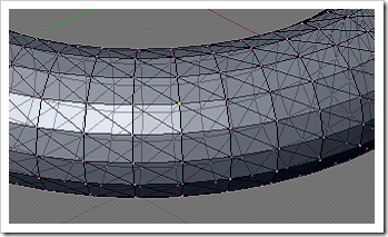
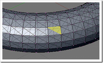
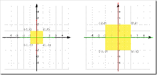
A vertex (vertices in plural) is the smallest building block of 3D model. A vertex is a point where two or more edges meet. In a 3D model a vertex can be shared between all connected edges, paces and polygons. A vertex can also be a represent for the position of a camera or a light source. You can see a vertex in the image below marked in yellow.
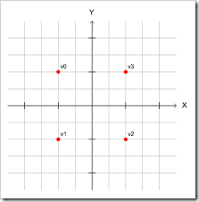 To define the vertices on android we define them as a float array that we put into a byte buffer to gain better performance. Look at the image to the right and the code below to match the vertices marked on the image to the code.
private float vertices[] = {
-1.0f, 1.0f, 0.0f, // 0, Top Left
-1.0f, -1.0f, 0.0f, // 1, Bottom Left
1.0f, -1.0f, 0.0f, // 2, Bottom Right
1.0f, 1.0f, 0.0f, // 3, Top Right
};
// a float is 4 bytes, therefore we multiply the number if vertices with 4.
ByteBuffer vbb = ByteBuffer.allocateDirect(vertices.length * 4);
vbb.order(ByteOrder.nativeOrder());
FloatBuffer vertexBuffer = vbb.asFloatBuffer();
vertexBuffer.put(vertices);
vertexBuffer.position(0);
Don't forget that a float is 4 bytes and to multiply it with the number of vertices to get the right size on the allocated buffer.
OpenGL ES have a pipeline with functions to apply when you tell it to render. Most of these functions are not enabled by default so you have to remember to turn the ones you like to use on. You might also need to tell these functions what to work with. So in the case of our vertices we need to tell OpenGL ES that it’s okay to work with the vertex buffer we created we also need to tell where it is.
// Enabled the vertex buffer for writing and to be used during rendering.
gl.glEnableClientState(GL10.GL_VERTEX_ARRAY);// OpenGL docs.
// Specifies the location and data format of an array of vertex
// coordinates to use when rendering.
gl.glVertexPointer(3, GL10.GL_FLOAT, 0, vertexBuffer); // OpenGL docs.
When you are done with the buffer don't forget to disable it.
// Disable the vertices buffer.
gl.glDisableClientState(GL10.GL_VERTEX_ARRAY);// OpenGL docs.
Edge
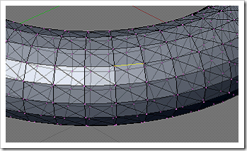
Edge is a line between two vertices. They are border lines of faces and polygons. In a 3D model an edge can be shared between two adjacent faces or polygons. Transforming an edge affects all connected vertices, faces and polygons. In OpenGL ES you don't define the edges, you rather define the face by giving them the vertices that would build up the three edges. If you would like modify an edge you change the two vertices that makes the edge. You can see an edge in the image below marked in yellow.
Face
Face is a triangle. Face is a surface between three corner vertices and three surrounding edges. Transforming a face affects all connected vertices, edges and polygons.
The order does matter.
When winding up the faces it's important to do it in the right direction because the direction defines what side will be the front face and what side will be the back face. Why this is important is because to gain performance we don't want to draw both sides so we turn off the back face. So it's a good idea to use the same winding all over your project. It is possible to change what direction that defines the front face with glFrontFace.
gl.glFrontFace(GL10.GL_CCW); // OpenGL docs
To make OpenGL skip the faces that are turned into the screen you can use something called back-face culling. What is does is determines whether a polygon of a graphical object is visible by checking if the face is wind up in the right order.
gl.glEnable(GL10.GL_CULL_FACE); // OpenGL docs
It's ofcource possible to change what face side should be drawn or not.
gl.glCullFace(GL10.GL_BACK); // OpenGL docs
Polygon
 Time to wind the faces, remember we have decided to go with the default winding meaning counter-clockwise. Look at the image to the right and the code below to see how to wind up this square.
private short[] indices = { 0, 1, 2, 0, 2, 3 };
To gain some performance we also put this ones in a byte buffer.
// short is 2 bytes, therefore we multiply the number if vertices with 2.
ByteBuffer ibb = ByteBuffer.allocateDirect(indices.length * 2);
ibb.order(ByteOrder.nativeOrder());
ShortBuffer indexBuffer = ibb.asShortBuffer();
indexBuffer.put(indices);
indexBuffer.position(0);
Don't forget that a short is 2 bytes and to multiply it with the number of indices to get the right size on the allocated buffer.
Render
Time to get something on the screen, there is two functions used to draw and we have to decide which one to use.
The two functions are:
public abstract void glDrawArrays(int mode, int first, int count) // OpenGL docs
glDrawArrays draws the vertices in that order they are specified in the construction of our verticesBuffer.
public abstract void glDrawElements(int mode, int count, int type, // OpenGL docs
Buffer indices)
glDrawElements need a little bit more to be able to draw. It needs to know the order which to draw the vertices, it needs the indicesBuffer.
Since we already created the indicesBuffer I'm guessing that you figured out that's the way we are going.
What is common for this functions is that they both need to know what it is they should draw, what primitives to render. Since there is some various ways to render this indices and some of them are good to know about for debugging reasons. I'll go through them all.
What primitives to render
GL_POINTS
Draws individual points on the screen.
GL_LINE_STRIP
Series of connected line segments.
GL_LINE_LOOP
Same as above, with a segment added between last and first vertices.
GL_LINES
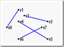
Pairs of vertices interpreted as individual line segments.
GL_TRIANGLES
Triples of vertices interpreted as triangles.
GL_TRIANGLE_STRIP
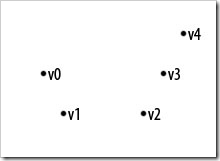
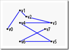
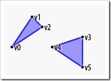
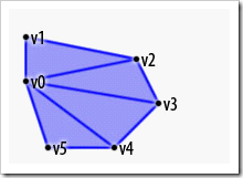
Draws a series of triangles (three-sided polygons) using vertices v0, v1, v2, then v2, v1, v3 (note the order), then v2, v3, v4, and so on. The ordering is to ensure that the triangles are all drawn with the same orientation so that the strip can correctly form part of a surface.
GL_TRIANGLE_FAN
Same as GL_TRIANGLE_STRIP, except that the vertices are drawn v0, v1, v2, then v0, v2, v3, then v0, v3, v4, and so on.
I think the GL_TRIANGLES is the easiest to use so we go with that one for now.
Putting it all togetter
So let's putting our square together in a class.
package se.jayway.opengl.tutorial;
import java.nio.ByteBuffer;
import java.nio.ByteOrder;
import java.nio.FloatBuffer;
import java.nio.ShortBuffer;
import javax.microedition.khronos.opengles.GL10;
public class Square {
// Our vertices.
private float vertices[] = {
-1.0f, 1.0f, 0.0f, // 0, Top Left
-1.0f, -1.0f, 0.0f, // 1, Bottom Left
1.0f, -1.0f, 0.0f, // 2, Bottom Right
1.0f, 1.0f, 0.0f, // 3, Top Right
};
// The order we like to connect them.
private short[] indices = { 0, 1, 2, 0, 2, 3 };
// Our vertex buffer.
private FloatBuffer vertexBuffer;
// Our index buffer.
private ShortBuffer indexBuffer;
public Square() {
// a float is 4 bytes, therefore we multiply the number if
// vertices with 4.
ByteBuffer vbb = ByteBuffer.allocateDirect(vertices.length * 4);
vbb.order(ByteOrder.nativeOrder());
vertexBuffer = vbb.asFloatBuffer();
vertexBuffer.put(vertices);
vertexBuffer.position(0);
// short is 2 bytes, therefore we multiply the number if
// vertices with 2.
ByteBuffer ibb = ByteBuffer.allocateDirect(indices.length * 2);
ibb.order(ByteOrder.nativeOrder());
indexBuffer = ibb.asShortBuffer();
indexBuffer.put(indices);
indexBuffer.position(0);
}
/**
* This function draws our square on screen.
* @param gl
*/
public void draw(GL10 gl) {
// Counter-clockwise winding.
gl.glFrontFace(GL10.GL_CCW); // OpenGL docs
// Enable face culling.
gl.glEnable(GL10.GL_CULL_FACE); // OpenGL docs
// What faces to remove with the face culling.
gl.glCullFace(GL10.GL_BACK); // OpenGL docs
// Enabled the vertices buffer for writing and to be used during
// rendering.
gl.glEnableClientState(GL10.GL_VERTEX_ARRAY);// OpenGL docs.
// Specifies the location and data format of an array of vertex
// coordinates to use when rendering.
gl.glVertexPointer(3, GL10.GL_FLOAT, 0, // OpenGL docs
vertexBuffer);
gl.glDrawElements(GL10.GL_TRIANGLES, indices.length,// OpenGL docs
GL10.GL_UNSIGNED_SHORT, indexBuffer);
// Disable the vertices buffer.
gl.glDisableClientState(GL10.GL_VERTEX_ARRAY); // OpenGL docs
// Disable face culling.
gl.glDisable(GL10.GL_CULL_FACE); // OpenGL docs
}
}
We have to initialize our square in the OpenGLRenderer class.
// Initialize our square.
Square square = new Square();
And in the draw function call on the square to draw.
public void onDrawFrame(GL10 gl) {
// Clears the screen and depth buffer.
gl.glClear(GL10.GL_COLOR_BUFFER_BIT | // OpenGL docs.
GL10.GL_DEPTH_BUFFER_BIT);
// Draw our square.
square.draw(gl); // ( NEW )
}
If you run the application now the screen is still black. Why? Because OpenGL ES render from where the current position is, that by default is at point: 0, 0, 0 the same position that the view port is located. And OpenGL ES don’t render the things that are too close to the view port. The solution to this is to move the draw position a few steps into the screen before rendering the square:
// Translates 4 units into the screen.
gl.glTranslatef(0, 0, -4); // OpenGL docs
I will talk about the different transformations in the next tutorial.
Run the application again and you will see that the square is drawn but quickly moves further and further into the screen. OpenGL ES doesn’t reset the drawing point between the frames that you will have to do yourself:
// Replace the current matrix with the identity matrix
gl.glLoadIdentity(); // OpenGL docs
Now if you run the application you will see the square on a fixed position.
OpenGL ES Tutorial for Android
– Part III
Last tutorial was about building your polygons. This tutorial is all about transformations, how to move the polygons around. I will continue this tutorial from where the previous ended so you can use that source code or make a copy of it.
I am not going to bore you with a lot of mathematics but I believe it is important to know that when OpenGL render a mesh it multiplies all vertices with a matrix. All the transformations you do are about manipulating the vertices in different ways by modifying this matrix. You can think of the matrix as a paper and that you never move the pen before you start to draw. You always draw in the center. But by doing a translation on the matrix you are moving the paper and also the center. A rotation is like rotating the paper around the center. And a scale is a bit harder to visualize with the paper view but it is like changing the unit size regarding to how you translate your meshes. Usually you talk about transformations according to the mesh not the world, but it is still important to know about.
Coordinate System
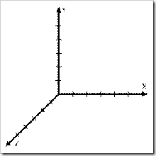
OpenGL uses a so called right-handed coordinate system. A system is called right-handed if you look from the positive end towards the origin of the axis the counter-clockwise rotation is considered to be a positive rotation.
When you have started up your view and haven't applied any transformations the axis are aligned like this: The x-axis goes from left to right, the y-axis comes from the bottom and goes up and the z-axis is moving from the back of the screen towards the front of the screen.
Translate
public abstract void glTranslatef (float x, float y, float z) //OpenGL docs.
 A translations added to the matrix makes the mesh appear as it has been moved. Translations are made along the axis and with no rotation added the axis are in there default state. Translation affects all the vertices in a polygon the same amount over the same axis. Translations are simply additions and subtractions to a current value. The image to the right shows a translation in 2 dimensions.
The start point is {x:-2, y:1} we like to go to {x:1, y:3} so we add {x:3, y:2}.
A simple addition: {x:-2, y:1} + {x:3, y:2} = {x:-2 + 3, y:1 + 2} = {x:1, y:3}.
In 3 dimensions we do the same, if we are located at position: {x:1, y:1, z:0} and we like to move 3 units into the screen we add {x:0, y:0, z:-3} and end up at: {x:1, y:1, z:-3}.
In the last tutorial we moved the square 4 units into the screen just to be able to see the square. What we did was that we added {x:0, y:0, z:-4} to the current position. This is the code we used for the translation:
// Translates 4 units into the screen.
gl.glTranslatef(0, 0, -4); OpenGL docs.
If you do several translations after each other the order of the movement is along the X, Y and Z axis, in that order. On translate the order isn't so important but when we do a rotation it's really important.
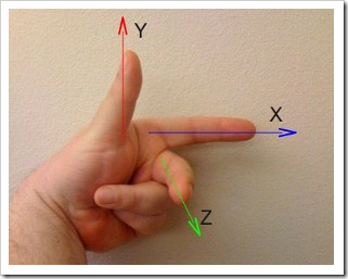
It can be quite tricky to remember how the axis are aligned. Fortunate there is a good trick to remember the direction of the axis. Hold your left hand like the photo below. The point on each finger represents the positive direction on one axis. Your thumb is y-axis, index finger is x-axis and your middle finger would represent the z-axis. When I first started with 3D programming I actually wrote the letters, x, y and z on my fingers ![]()
Rotate
public abstract void glRotatef(float angle, float x, float y, float z)//OpenGL docs.
If you remember these three things you will manage rotation quite easy.
1. The rotation value are in degrees.
Most frameworks and math functions on computers use radians but OpenGL use degrees.
2. When doing several rotations the order are important.
If you like to restore a rotation you negate the angle or all the axis like this: glRotatef(angle, x, y, z) is restored with glRotatef(angle, -x, -y, -z) or glRotatef(-angle, x, y, z).
But if you do several rotations after each other like this:
gl.glRotatef(90f, 1.0f, 0.0f, 0.0f); // OpenGL docs.
gl.glRotatef(90f, 0.0f, 1.0f, 0.0f); // OpenGL docs.
gl.glRotatef(90f, 0.0f, 0.0f, 1.0f); // OpenGL docs.
And want to restore the mesh to it's original position you can't just negate the angle like this:
gl.glRotatef(90f, -1.0f, 0.0f, 0.0f); // OpenGL docs.
gl.glRotatef(90f, 0.0f, -1.0f, 0.0f); // OpenGL docs.
gl.glRotatef(90f, 0.0f, 0.0f, -1.0f); // OpenGL docs.
You have to revert the order of the rotations as well like this:
gl.glRotatef(90f, 0.0f, 0.0f, -1.0f); // OpenGL docs.
gl.glRotatef(90f, 0.0f, -1.0f, 0.0f); // OpenGL docs.
gl.glRotatef(90f, -1.0f, 0.0f, 0.0f); // OpenGL docs.
The order of several rotations is important.
3. If you look from the positive end towards the origin of the axis the positive rotation is counter-clockwise.
If you take a pencil in your hand, let the point be in the same direction as your thumb, as in the picture below, then aligns the pencil with the x-axis. Let the pencil's point be aligned with the positive direction of the axis. Your other fingers will now point in the positive direction of the rotation over that axis.
Translate & Rotate
Since both rotation and translations are made within each mesh own coordinate system it is important to remember that the order you do the translation and rotation are very important.
If you do a translation on the mesh first and then rotate it, the translation is made on the current state of the mesh coordinate system and then rotated at the new location.
If you first rotate and the move the mesh it will be moved accordingly to its own rotated coordinate system.
Scale
public abstract void glScalef (float x, float y, float z) // OpenGL docs.
Scaling is just as it sounds and it is possible to scale over each axis separately. Scaling is the same as multiplying all vertexes with the same scalar. In the image below we scale with: gl.glScalef(2f, 2f, 2f). That means that we multiply all vertixes with 2.
Translate & Scale
The order of scaling and translating does matter. If you translate before scaling the transformation is intact. Like this example, first a translation of 2 units and then scale it by 0.5.
gl.glTranslatef(2, 0, 0); // OpenGL docs.
gl.glScalef(0.5f, 0.5f, 0.5f); // OpenGL docs.
But if you scale before the translation you get a different result. Since you scale the mesh coordinate system then do the translation you will not move the mesh the same amount as you would before the scaling. So if you first scale with 0.5 and then do a translation of 2 units the result will appear as a translation of 1 unit.
gl.glScalef(0.5f, 0.5f, 0.5f); // OpenGL docs.
gl.glTranslatef(2, 0, 0); // OpenGL docs.
Load Identity, push and pop matrix
When you translate, rotate or scaling you are not applying the transformation from the same preconditions, you are applying them to the previous transition. You need to be able to reset the position.
glLoadIdentity
public abstract void glLoadIdentity() // OpenGL docs.
glLoadIdentity replaces the current matrix with the identity matrix. It is the same as calling glLoadMatrix with the identity matrix:
1 0 0 0
0 1 0 0
0 0 1 0
0 0 0 1
There are situations where you don't want to reset the model matrix, you rather want to go back to how it was just before your latest transformation.
glPushMatrix
public abstract void glPushMatrix() // OpenGL docs.
glPushMatrix makes a copy of the current matrix and put it on the stack. This means that when you do any kind of translations after glPushMatrix you are doing them on a copy.
glPopMatrix
public abstract void glPopMatrix() // OpenGL docs.
To get back to the previous matrix you use the glPushMatrix command.
A good practice can be to have one glLoadIdentity in the begining of each frame and after that use glPushMatrix and glPopMatrix.
Putting it all togetter
So to make something with this new knowlege let us do 3 squares call them A, B and C. Scale them so that B is 50% smaller then A and C is 50% smaller then B. Then let A rotate counter-clockwise in the center of the screen. B should rotate clockwise around A and finaly C rotating clockwise around B and counter-clockwise in a high speed around it's own center.
public void onDrawFrame(GL10 gl) {
// Clears the screen and depth buffer.
gl.glClear(GL10.GL_COLOR_BUFFER_BIT | GL10.GL_DEPTH_BUFFER_BIT);
// Replace the current matrix with the identity matrix
gl.glLoadIdentity();
// Translates 10 units into the screen.
gl.glTranslatef(0, 0, -10);
// SQUARE A
// Save the current matrix.
gl.glPushMatrix();
// Rotate square A counter-clockwise.
gl.glRotatef(angle, 0, 0, 1);
// Draw square A.
square.draw(gl);
// Restore the last matrix.
gl.glPopMatrix();
// SQUARE B
// Save the current matrix
gl.glPushMatrix();
// Rotate square B before moving it, making it rotate around A.
gl.glRotatef(-angle, 0, 0, 1);
// Move square B.
gl.glTranslatef(2, 0, 0);
// Scale it to 50% of square A
gl.glScalef(.5f, .5f, .5f);
// Draw square B.
square.draw(gl);
// SQUARE C
// Save the current matrix
gl.glPushMatrix();
// Make the rotation around B
gl.glRotatef(-angle, 0, 0, 1);
gl.glTranslatef(2, 0, 0);
// Scale it to 50% of square B
gl.glScalef(.5f, .5f, .5f);
// Rotate around it's own center.
gl.glRotatef(angle*10, 0, 0, 1);
// Draw square C.
square.draw(gl);
// Restore to the matrix as it was before C.
gl.glPopMatrix();
// Restore to the matrix as it was before B.
gl.glPopMatrix();
// Increse the angle.
angle++;
}
And don't forget to add angel as a variable as well. Thanks Tim!
public class OpenGLRenderer implements Renderer {
private Square square;
private float angle; // Don't forget to add this.
...
OpenGL ES Tutorial for Android
– Part IV
Last tutorial was about transformations. This tutorial will be a short one. I'm going to talk about adding color to your mesh. I will continue with the source code from tutorial II.
Adding color
3D models with no colors are pretty boring so let's add some color to it. In general colors need no explanation. OpenGL ES uses a color model called RGBA ( Red, Green, Blue and Alpha ). The first three are self explained. The fourth is transparency, how solid the color should be. If you like to read more about colors go to: RGB color model - Wikipedia, the free encyclopedia
You might be familiar with defining colors with hex (#FF00FF) or with decimals (255, 0, 255) we will use 0..1 where 0 map to 0 (#00) and 1 map against 255 (#FF).
The easiest way of coloring meshes is called vertex coloring and I am going to show you two different ways of doing that. Flat coloring that gives one solid color and smooth coloring that will blend colors specified for each vertex. Texturing is also a way of giving your mesh colors but it is not vertex coloring so I will show you how to do that in a later tutorial.
Flat coloring
 Flat coloring is really easy just tell OpenGL ES what color to use when it is going to render. One thing to remember is that when you set the color OpenGL ES uses this color until you change the color. This means that if you have two different squares and you tell OpenGL ES to change the color right before the second square the first frame the two squares will have different color but the next rendered frame both squares will have the same color.
To tell OpenGL ES what color to work with you use this command:
public abstract void glColor4f(float red, float green, float blue, float alpha)
The default values are: red = 1, green = 1, blue = 1 and alpha = 1. Those values are white, and that's why all the squares we previous made has a white color.
Create a new class called FlatColoredSquare it should be identical to the Square class. Then in the FlatColoredSquare function draw, add this line:
gl.glColor4f(0.5f, 0.5f, 1.0f, 1.0f); // 0x8080FFFF
I usually add a comment like the one above ( // 0x8080FFFF ) because I am used to read that. It makes it easier for me when reviewing the code.
It should now look like this:
public void draw(GL10 gl) {
gl.glColor4f(0.5f, 0.5f, 1.0f, 1.0f);
...
Then change in the renderer so it uses the FlatColoredSquare instead of the Square.
public class OpenGLRenderer implements Renderer {
private FlatColoredSquare flatSquare; // CHANGED
public OpenGLRenderer() {
// Initialize our square.
flatSquare = new FlatColoredSquare(); // CHANGED
}
public void onDrawFrame(GL10 gl) {
...
flatSquare.draw(gl); // Don't forget to change this one.
...
}
Remember that anything rendered after you set a color uses the same color and that this spans over frames and will not be reset in-between.
If you compile and run the application you will see one big flat colored blue square.
Just to give place to the smooth colored square coming up we move the flat square up.
public void onDrawFrame(GL10 gl) {
gl.glLoadIdentity();
// Translates 7 units into the screen and 1.5 units up.
gl.glTranslatef(0, 1.5f, -7);
// Draw our flat square.
flatSquare.draw(gl);
}
Notice that with flat coloring you don't need to tell OpenGL ES to turn it on or off. OpenGL ES uses flat coloring as a default way of coloring the meshes.
Smooth coloring
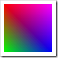 Smooth coloring is gained when you give each vertex its own color. OpenGL ES will interpolate the colors between the vertices and you will gain a smooth coloring effect. Just as with the flat coloring you tell OpenGL ES what to work with and it will be used as long as you don't say anything else.
Create a new class called SmoothColoredSquare it should be identical to the Square class just as you did with the FlatColoredSquare. Modify the new class with this:
Define the colors you like your vertices to have.
public class SmoothColoredSquare {
...
// The colors mapped to the vertices.
float[] colors = {
1f, 0f, 0f, 1f, // vertex 0 red
0f, 1f, 0f, 1f, // vertex 1 green
0f, 0f, 1f, 1f, // vertex 2 blue
1f, 0f, 1f, 1f, // vertex 3 magenta
};
...
The order of defining the colors are important since they map against the vertices so in this example above the first color (1f, 0f, 0f, 1f ) map against the top left vertex ( -1.0f, 1.0f, 0.0f ) the green against the bottom left vertex and the rest you can figure out. Hint: Look at the image above.
And put them in a buffer just as we did with the vertices and indices.
public SmoothColoredSquare() {
...
// float has 4 bytes, colors (RGBA) * 4 bytes
ByteBuffer cbb = ByteBuffer.allocateDirect(colors.length * 4);
cbb.order(ByteOrder.nativeOrder());
colorBuffer = cbb.asFloatBuffer();
colorBuffer.put(colors);
colorBuffer.position(0);
}
Don't forget to add colorBuffer as a variable to the class as well.
// Our color buffer.
private FloatBuffer colorBuffer;
We also need to enable the color buffer and tell openGL where it is.
public void draw(GL10 gl) {
...
gl.glVertexPointer(3, GL10.GL_FLOAT, 0, vertexBuffer);
// Enable the color array buffer to be used during rendering.
gl.glEnableClientState(GL10.GL_COLOR_ARRAY); // NEW LINE ADDED.
// Point out the where the color buffer is.
gl.glColorPointer(4, GL10.GL_FLOAT, 0, colorBuffer); // NEW LINE ADDED.
gl.glDrawElements(GL10.GL_TRIANGLES, indices.length,
GL10.GL_UNSIGNED_SHORT, indexBuffer);
...
// Disable the color buffer.
gl.glDisableClientState(GL10.GL_COLOR_ARRAY);
...
}
Don't forget to disable the use of the color array. If you don't disable the color array both squares will be smooth colored. Try it.
Let's use this new smooth square as well. Start by adding it to your renderer.
public class OpenGLRenderer implements Renderer {
private FlatColoredSquare flatSquare;
private SmoothColoredSquare smoothSquare; // NEW LINE ADDED.
public OpenGLRenderer() {
// Initialize our squares.
flatSquare = new FlatColoredSquare();
smoothSquare = new SmoothColoredSquare(); // NEW LINE ADDED.
}
We need to move the square down a bit so they don't collide.
public void onDrawFrame(GL10 gl) {
...
// Translate to end up under the flat square.
gl.glTranslatef(0, -3f, 0);
// Draw our smooth square.
smoothSquare.draw(gl);
}
Now if you compile and run the application you will see two squares, one solid blue and one smooth with different colors.
OpenGL ES Tutorial for Android
– Part V
I have a feeling that some of you have tried my tutorials and then thought "This is a 3D tutorial, but why is everything in 2D?". So in this tutorial we will make some real 3D meshes. This is also necessary for the following tutorials.
When I started I had problems with finding out how to programmatic make different meshes like cubes, cones and so on. I needed this so I easy easy could put my scenes together. So this tutorial will show how to make some of the basic primitives. They might not be the most effective way of creating them but it is a way of doing them.
Starting point will be from the source of the second tutorial. I will show you plane and cube and then give you a couple of hint for additional primitives.
Design
A good place to start when designing an OpenGL framework is to use the composite pattern. This is a start of how I would proceed:
Let's start making out pattern.
Mesh
It's a good idea to have a common base for your meshes. So let us start by creating a class called Mesh.
package se.jayway.opengl.tutorial.mesh;
public class Mesh {
}
We add the draw function from previous example, since I when over this function in a previous tutorial I just show it here:
// Our vertex buffer.
private FloatBuffer verticesBuffer = null;
// Our index buffer.
private ShortBuffer indicesBuffer = null;
// The number of indices.
private int numOfIndices = -1;
// Flat Color
private float[] rgba = new float[]{1.0f, 1.0f, 1.0f, 1.0f};
// Smooth Colors
private FloatBuffer colorBuffer = null;
public void draw(GL10 gl) {
// Counter-clockwise winding.
gl.glFrontFace(GL10.GL_CCW);
// Enable face culling.
gl.glEnable(GL10.GL_CULL_FACE);
// What faces to remove with the face culling.
gl.glCullFace(GL10.GL_BACK);
// Enabled the vertices buffer for writing and to be used during
// rendering.
gl.glEnableClientState(GL10.GL_VERTEX_ARRAY);
// Specifies the location and data format of an array of vertex
// coordinates to use when rendering.
gl.glVertexPointer(3, GL10.GL_FLOAT, 0, verticesBuffer);
// Set flat color
gl.glColor4f(rgba[0], rgba[1], rgba[2], rgba[3]);
// Smooth color
if ( colorBuffer != null ) {
// Enable the color array buffer to be used during rendering.
gl.glEnableClientState(GL10.GL_COLOR_ARRAY);
// Point out the where the color buffer is.
gl.glColorPointer(4, GL10.GL_FLOAT, 0, colorBuffer);
}
gl.glDrawElements(GL10.GL_TRIANGLES, numOfIndices,
GL10.GL_UNSIGNED_SHORT, indicesBuffer);
// Disable the vertices buffer.
gl.glDisableClientState(GL10.GL_VERTEX_ARRAY);
// Disable face culling.
gl.glDisable(GL10.GL_CULL_FACE);
}
We need functions where the subclasses can set the vertices and the indices. These function contains nothing new and are pretty much the same as you seen in earlier tutorials.
protected void setVertices(float[] vertices) {
// a float is 4 bytes, therefore we multiply the number if
// vertices with 4.
ByteBuffer vbb = ByteBuffer.allocateDirect(vertices.length * 4);
vbb.order(ByteOrder.nativeOrder());
verticesBuffer = vbb.asFloatBuffer();
verticesBuffer.put(vertices);
verticesBuffer.position(0);
}
protected void setIndices(short[] indices) {
// short is 2 bytes, therefore we multiply the number if
// vertices with 2.
ByteBuffer ibb = ByteBuffer.allocateDirect(indices.length * 2);
ibb.order(ByteOrder.nativeOrder());
indicesBuffer = ibb.asShortBuffer();
indicesBuffer.put(indices);
indicesBuffer.position(0);
numOfIndices = indices.length;
}
protected void setColor(float red, float green, float blue, float alpha) {
// Setting the flat color.
rgba[0] = red;
rgba[1] = green;
rgba[2] = blue;
rgba[3] = alpha;
}
protected void setColors(float[] colors) {
// float has 4 bytes.
ByteBuffer cbb = ByteBuffer.allocateDirect(colors.length * 4);
cbb.order(ByteOrder.nativeOrder());
colorBuffer = cbb.asFloatBuffer();
colorBuffer.put(colors);
colorBuffer.position(0);
}
We need to add a couple of things. When we start working with multiple meshes we need to be able to move and rotate them individual so let us add translation and rotation parameters:
// Translate params.
public float x = 0;
public float y = 0;
public float z = 0;
// Rotate params.
public float rx = 0;
public float ry = 0;
public float rz = 0;
And use them in the draw function add this lines just before the gl.glDrawElements call.
gl.glTranslatef(x, y, z);
gl.glRotatef(rx, 1, 0, 0);
gl.glRotatef(ry, 0, 1, 0);
gl.glRotatef(rz, 0, 0, 1);
Plane
Let us start making a plane an quite easy task you might think and it kinda is. But to make it more interesting and more useful we need to be able to create it with some different settings like: width, depth, how many width segments and how many depth segments.
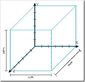
Just so we have the same terminology, width is the length over the x-axis, depth is over the z-axis and height is over the y-axis. Look at the image below as a visual input.
Width, height and depth.
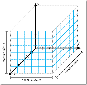
Segments is how many parts the length should be divided by. This is useful if you need to make a surface that is not total even. If you create a plane over x, y and make z not all be 0 say you give z a random span from -0.1 to 0.1 you will get something you could use as a ground plane in a game just put a nice texture on it.
Segments.
Looking at the image above you see that the different segments gives you squares. Since we like it to be triangles so just split them up into 2 triangles.
I hate frameworks and classes that don't have a default setup and easy class constructors I try to always have more then one constructor. The constructors I will put in this plane is:
For an easy and quick setup:
// Gives you a plane that is 1 unit wide and 1 unit high with just one segment over width and height.
public Plane()
An easy one just to change the size:
// Let you decide the size of the plane but still only one segment.
public Plane(float width, float height)
And finally one for setting up the plane with different segments:
// For alla your settings.
public Plane(float width, float height, int widthSegments, int heightSegments)
If I in theory would construct a plane that is 1 unit wide and 1 units high with 4 segments in both width and height direction it would look like this images:
The one to the left shows the segments and the one to the right show us the faces we need to create.
package se.jayway.opengl.tutorial.mesh;
public class Plane extends Mesh {
public Plane() {
this(1, 1, 1, 1);
}
public Plane(float width, float height) {
this(width, height, 1, 1);
}
public Plane(float width, float height, int widthSegments,
int heightSegments) {
float[] vertices = new float[(widthSegments + 1) * (heightSegments + 1)
* 3];
short[] indices = new short[(widthSegments + 1) * (heightSegments + 1)
* 6];
float xOffset = width / -2;
float yOffset = height / -2;
float xWidth = width / (widthSegments);
float yHeight = height / (heightSegments);
int currentVertex = 0;
int currentIndex = 0;
short w = (short) (widthSegments + 1);
for (int y = 0; y < heightSegments + 1; y++) {
for (int x = 0; x < widthSegments + 1; x++) {
vertices[currentVertex] = xOffset + x * xWidth;
vertices[currentVertex + 1] = yOffset + y * yHeight;
vertices[currentVertex + 2] = 0;
currentVertex += 3;
int n = y * (widthSegments + 1) + x;
if (y < heightSegments && x < widthSegments) {
// Face one
indices[currentIndex] = (short) n;
indices[currentIndex + 1] = (short) (n + 1);
indices[currentIndex + 2] = (short) (n + w);
// Face two
indices[currentIndex + 3] = (short) (n + 1);
indices[currentIndex + 4] = (short) (n + 1 + w);
indices[currentIndex + 5] = (short) (n + 1 + w - 1);
currentIndex += 6;
}
}
}
setIndices(indices);
setVertices(vertices);
}
}
Cube
The next step I think a cube will be nice. I will only make a cube that you can set: height, width and depth on but I suggest you as a practice make it with segments just as we did with the plane.
The constructor will look like this:
public Cube(float width, float height, float depth)
And since I'm not doing this with any segments the constructor will be quite easy.
package se.jayway.opengl.tutorial.mesh;
public class Cube extends Mesh {
public Cube(float width, float height, float depth) {
width /= 2;
height /= 2;
depth /= 2;
float vertices[] = { -width, -height, -depth, // 0
width, -height, -depth, // 1
width, height, -depth, // 2
-width, height, -depth, // 3
-width, -height, depth, // 4
width, -height, depth, // 5
width, height, depth, // 6
-width, height, depth, // 7
};
short indices[] = { 0, 4, 5,
0, 5, 1,
1, 5, 6,
1, 6, 2,
2, 6, 7,
2, 7, 3,
3, 7, 4,
3, 4, 0,
4, 7, 6,
4, 6, 5,
3, 0, 1,
3, 1, 2, };
setIndices(indices);
setVertices(vertices);
}
}
If you like to make it with segments the constructor could look like this:
public Cube(float width, float height, float depth,
int widthSegments, int heightSegments, int depthSegments)
Since we now have a plane that replaces the Square class ( in the code from tutorial II ) I will just remove it and in OpenGLRenderer change the square to a cube...
public OpenGLRenderer() {
// Initialize our cube.
cube = new Cube(1, 1, 1);
cube.rx = 45;
cube.ry = 45;
}
... and render it.
public void onDrawFrame(GL10 gl) {
...
// Draw our cube.
cube.draw(gl);
}
Group
A group is really good to have when setting up and controlling your 3D scene. What a group really do is to distribute all commands sent to the group to all it's children. You can see the implementation of a simple group here:
package se.jayway.opengl.tutorial.mesh;
import java.util.Vector;
import javax.microedition.khronos.opengles.GL10;
public class Groupextends Mesh {
private Vector<Mesh> children = new Vector<Mesh>();
@Override
public void draw(GL10 gl) {
int size = children.size();
for( int i = 0; i < size; i++)
children.get(i).draw(gl);
}
public void add(int location, Mesh object) {
children.add(location, object);
}
public boolean add(Mesh object) {
return children.add(object);
}
public void clear() {
children.clear();
}
public Mesh get(int location) {
return children.get(location);
}
public Mesh remove(int location) {
return children.remove(location);
}
public boolean remove(Objectobject) {
return children.remove(object);
}
public int size() {
return children.size();
}
}
Make the renderer work with a group as a root node and add your cube to it.
Cube cube = new Cube(1, 1, 1);
cube.rx = 45;
cube.ry = 45;
group.add(cube);
root = group;
And draw our scene:
public void onDrawFrame(GL10 gl) {
...
// Draw our scene.
root.draw(gl);
}
Suggestions
It's always a good idea to have different primitives ready to use when you starting up a new project. My experience tell me that in 9 times of 10 you won't have any meshes from the graphic people when you start coding so it's really good to have some meshes to work with as place holders. I'll give you a hint of the way to start with your own meshes library by giving you an idea of how I would do it.
Creating your own meshes is a really good way of getting to know vertices and indices really close up.
Cone
After you have gotten your cube up and ready to go my suggestion is that you move onto a cone. A cone with the right settings could be more then just a cone. if you give is 3-4 sides it will be a pyramid. If you give it the same base and top radius it becomes a cylinder. So you can see why it is so useful. Take a look at this image and see what the this cone can do.
public Cone(float baseRadius, float topRadius, float height, int numberOfSides)
Pyramid
public class Pyramid extends Cone {
public Pyramid(float baseRadius, float height) {
super(baseRadius, 0, height, 4);
}
}
Cylinder
public class Cylinder extends Cone {
public Cylinder(float radius, float height) {
super(radius, radius, height, 16);
}
}
One more thing
Dividing up surfaces is a good thing to know about and by now you know how to divide up a regular square. To divide up a triangle look at the images below. It is a bit different and it might be a bit harder to implement.
References
The info used in this tutorial is collected from:
Android Developers
OpenGL ES 1.1 Reference Pages
You can download the source for this tutorial here: Tutorial_Part_V
Previous tutorial: OpenGL ES Tutorial for Android – Part IV – Adding colors
Next tutorial:
Per-Erik Bergman
Consultant at Jayway











相关推荐
在Android上设置OpenGL ES视图是开发过程中的第一步,而`GLSurfaceView`是实现这一目标的关键组件。`GLSurfaceView`是Android 1.5引入的一个API类,它为OpenGL ES应用提供了基础框架和生命周期管理。以下是你需要...
OpenGL+ES应用开发实践指南++Android卷及书籍源码 非常好的资料
1.Android开发之OpenGL+ES教程 2.Android下Opengl+ES导引 3.OpenGL_ES_Programming_Guide_v1.0.2part1 4.OpenGL_ES_Programming_Guide_v1.0.2Part2 5.OpenGL + es + 2.0 + demo 6.OpenGL + ES + three + books 7....
### Android OpenGL ES 开发教程详解 #### 概述与历史沿革 OpenGL ES(OpenGL for Embedded Systems)作为OpenGL API的子集,专为移动设备、PDA和游戏主机等嵌入式系统设计,旨在简化3D图形应用的开发流程。自2003...
OpenGL+ES 应用开发指南 Android卷(美) OpenGL Android
OpenGL+ES应用开发实践指南(Android卷)(美)KevinBrothaler著.pdf ,适合新手学习,讲的很好
在Android设备上开发OpenGL ES应用时,需要注意兼容性问题,因为不同的设备可能支持不同的OpenGL ES版本。通常,你应该确保代码兼容最低支持的版本,并利用条件语句来适配不同版本的功能。 总之,通过这个系列的...
由资深Android开发专家根据OpenGLES2.0版本撰写,不仅系统地讲解了OpenGLES的核心概念、技术,以及Android的图形机制,还通过大量案例讲解了在Android上进行OpenGLES开发的方法和技巧。 《OpenGL ES应用开发实践...
android+opengl es+ndk学习三维android开发重要资料,底层c实现,很经典
由资深Android开发专家根据OpenGLES2.0版本撰写,不仅系统地讲解了OpenGLES的核心概念、技术,以及Android的图形机制,还通过大量案例讲解了在Android上进行OpenGLES开发的方法和技巧。 《OpenGL ES应用开发实践...
本教程主要探讨如何在Android系统上,利用OpenGLES2.0图形库来处理和显示从Camera获取的YUV原始数据。YUV是一种常见的颜色空间,广泛应用于视频编码和解码,因为它对带宽的要求相对较低,特别适合移动设备。 首先,...
最后,了解如何与硬件加速的OpenGLES API交互,以及熟悉GLSL语言(OpenGL Shading Language),是成为OpenGL ES 2.0专家的必经之路。通过编写高效、可读性强的着色器代码,可以创造出各种复杂的视觉效果,实现令人...
Android OpenGL ES 简明开发真正的3D图 ...Android平台提供的OpenGL ES API主要定义在包android.opengl ,javax.microedition.khronos.egl ,javax.microedition.khronos.opengles ,java.nio 等几个包中
基于 Android NDK 进行 OpenGL ES 开发的完整案例 Android NDK 和 OpenGL ES 简介 Android NDK(Native Development Kit)是一套工具集合,帮助开发者使用 C 或 C++ 语言开发 Android 应用程序的原生代码部分。...
在 Android 平台上,OpenGL ES 通常用于游戏开发、3D 图形渲染以及其他需要高性能图形处理的场景。 在 Android Studio 2.1.3 中,要实现一个使用 OpenGL ES 3.0 的旋转三角形,你需要遵循以下步骤: 1. **设置项目...
在Android系统中,OpenGLES 2.0是用于图形渲染的重要框架,支持3D图形和复杂的视觉效果。本教程旨在帮助开发者从零基础开始掌握OpenGLES 2.0,并通过实例Demo加深理解。 入门篇: 1. **环境配置**:首先,你需要...
同时为了便于读者的学习,《Android 3D游戏开发技术宝典:OpenGL ES 2.0》附赠的光盘中包含了书中所有案例的完整源代码,同时给出了最后3个完整大型3D游戏案例的讲解视频,最大限度地帮助读者快速掌握相应的开发技术...